Structure and Components of the Digāṁśa Yantra

The Digāṁśa Yantra is designed for measuring the azimuth and altitude of celestial objects. While Digāṁśa Yantras constructed at different Indian observatories share the same fundamental purpose, their structural designs exhibit certain variations. In particular, the Digāṁśa Yantra at Ujjain differs in several respects from those found at Jaipur and Varanasi. The instrument primarily consists of two concentric cylindrical walls and a central pillar positioned at their common center. Since the two walls are built with different radii, a circular passage is formed between them.

Structure and Components of the Digāṁśa Yantra

From a structural perspective, the Digāṁśa Yantra may be classified into the following two types:

Type 1
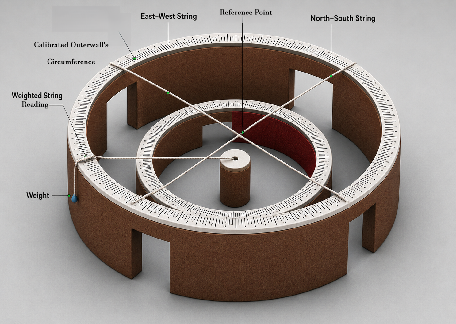
Digāṁśa Yantra — Vedh Shala Ujjain

In this configuration, the inner and outer cylindrical walls are of unequal height. The outer wall is approximately 2 metres high, whereas the inner wall and the central pillar are each about 1 metre high.

Two strings are stretched across the upper circumference of the outer wall along the north–south and east–west directions. Their point of intersection serves as a reference point. An additional weighted string is attached at one end to the midpoint of the central pillar, while its other end passes over the outer wall and hangs freely outside under a weight. The weighted string is adjusted so that the line of sight passing through both the reference point and the observed celestial object intersects the weighted string. In this situation, the point indicated by the weighted string on the graduated circumference of the outer wall then provides the azimuth of the celestial object.

Azimuth markings ranging from 0° to 360° are engraved along the upper circumference of the outer wall, enabling direct measurement of azimuth.

This type of Digāṁśa Yantra can be seen at the observatories of Jaipur and Varanasi.

Type 2
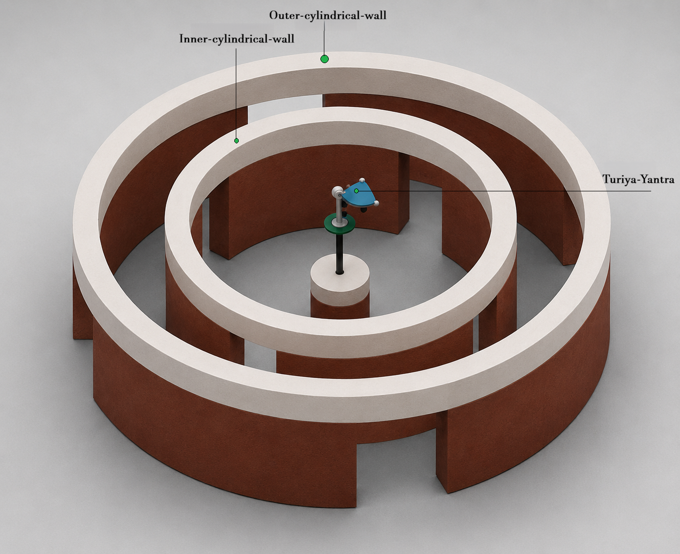
Digāṁśa Yantra — Vedh Shala Ujjain

In this configuration, both the inner and outer cylindrical walls are of nearly equal height, approximately 3 metres, while the central pillar remains about 1 metre high. An iron support is mounted at the center of the pillar, on which the Turiya instrument is installed.

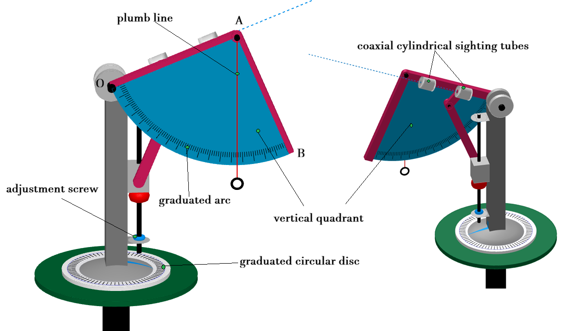
Celestial objects are observed through a set of coaxial apertures provided in the Turiya instrument. The altitude of a celestial object is determined using the vertical string and the graduated vertical quadrant scale attached to the instrument. The azimuth is read from the graduated circular disc located at the base of the Turiya instrument.

To align the instrument with a celestial object, the Turiya instrument can be rotated vertically using an adjustment screw, while the entire assembly can be rotated horizontally along the circular disc. This arrangement allows the observer to accurately target any celestial object and measure both its azimuth and altitude.

The Digāṁśa Yantra at Ujjain is based on this second configuration. Its principal components include the central pillar, a rotating sighting mechanism, the Turiya instrument, and a graduated quadrant scale. Working together, these elements enable relatively precise determination of the positions of celestial objects.
Working Principle

The Digāṁśa Yantra operates on the concept of azimuth, which is the angular position of a celestial object measured along the horizon from the true north direction in a clockwise sense. The instrument is designed to determine the horizontal position of celestial bodies by measuring their azimuth and, in certain configurations, their altitude.

Working Principle of the Type–1 Digāṁśa Yantra

In the Type–1 configuration, the azimuth of a celestial object is determined using the observer’s line of sight in conjunction with the geometric arrangement of the instrument.

The observer aligns the celestial object with the reference point formed by the intersection of the north–south and east–west strings stretched across the outer cylindrical wall. A weighted string attached to the central pillar is then adjusted so that it intersects the same line of sight.

When this alignment is achieved, the plane defined by the observer’s line of sight and the weighted string represents the azimuth plane of the celestial object. The angle between this azimuth plane and the local meridian plane corresponds to the azimuth of the object. The graduated mark indicated by the weighted string on the circumference of the outer wall therefore provides a direct reading of the object's azimuth.

Working Principle of the Type–2 Digāṁśa Yantra

Working Principle of the Digāṁśa Yantra

The operating principle of the Type–2 Digāṁśa Yantra is based primarily on the functionality of the Turiya Instrument. In this design, the concentric cylindrical walls serve mainly as structural elements, while the actual measurements are performed using the Turiya mechanism.

The Turiya Instrument incorporates a vertical quadrant (AOB), graduated from 0° to 90°. The quadrant can be rotated within its plane about its centre O using an adjustment screw. Attached to one arm (OA) are two coaxial cylindrical sighting tubes through which celestial objects are observed.

A plumb line is suspended from point A. In its initial position, arm OA is horizontal and the plumb line remains parallel to arm AB of the quadrant. Under these conditions, the plumb line indicates an altitude of 0° on the graduated arc.

As the quadrant is rotated upward to align the sighting tubes with a celestial object, the angle between the plumb line and arm AB changes accordingly. The point where the plumb line intersects the graduated arc directly indicates the altitude of the observed celestial object.

The entire Turiya Instrument can also be rotated horizontally about a vertical axis passing through its centre O. A graduated circular disc mounted at the base of the instrument records this horizontal rotation and is referenced to true north. The angular reading obtained from this disc provides the azimuth of the celestial object.

By combining vertical and horizontal adjustments, the instrument enables observers to accurately determine both the altitude and azimuth of celestial objects, thereby establishing their precise position within the local horizon coordinate system.

How to Perform Observations Using the Actual Instrument

Observation Procedure

Observation Procedure for the Type–1 Digāṁśa Yantra

Before measuring the azimuth of a celestial object, the following arrangements must be ensured:

  1. Horizontal strings should be stretched along the north–south and east–west directions across the upper circumference of the outer cylindrical wall. These strings should intersect directly above the central pillar. The point of intersection serves as the reference point for all observations.
  2. One end of a weighted string should be attached to the centre of the top of the central pillar, while the other end should extend beyond the outer wall and remain under tension by means of a suspended weight.
  3. The observation requires three observers:
    • Observer 1: Positioned within the circular corridor between the two cylindrical walls.
    • Observer 2: Located outside the outer wall and responsible for adjusting the weighted string.
    • Observer 3: Responsible for reading and recording the value indicated on the graduated scale of the outer wall.

Observation and Measurement

Observer 1 aligns their line of sight such that the observed celestial object, the reference point, and the observer's eye lie along the same straight line. Observer 2 then adjusts the weighted string until it also intersects this line of sight.

Once the celestial object, the reference point, and the weighted string are perfectly aligned, Observer 3 reads the graduation indicated by the string on the outer wall. This reading represents the azimuth of the celestial object.

Observation Procedure for the Type–2 Digāṁśa Yantra

The Turiya Instrument is first mounted on the central iron pillar. The instrument is then rotated in the horizontal plane and aligned with the true north direction, setting the azimuth indicator to 0°.

Using the adjustment screw and the horizontal rotation mechanism, the instrument is oriented until the celestial object can be clearly observed through the two sighting tubes.

In this position, the reading indicated by the plumb line on the graduated quadrant provides the altitude of the celestial object, while the pointer on the graduated circular disc at the base of the instrument indicates its azimuth.

The Digāṁśa Yantra (Type–1) Simulation

How to Use the Type–1 Digāṁśa Yantra Simulation

  1. Enter the latitude of the location for which the simulation is to be performed and press Enter.
  2. Use the Date slider to select any day of the year.
  3. Use the Time slider to set the desired time of day.
  4. As the date or time is changed, the apparent position of the Sun will automatically update in the simulation.
  5. The dotted line passing through the Sun and the reference point represents the line of sight.
  6. Adjust the weighted string using the Azimuth Angle slider until it intersects the line of sight.
  7. Once this alignment is achieved, the graduation indicated by the weighted string on the outer wall represents the azimuth of the Sun.

The Digāṁśa Yantra (Type–2) Simulation

Observation Procedure for the Type–2 Digamsha Yantra Simulation

  1. Begin by clicking the RESET button to restore the simulation to its default state.
  2. Use the mouse to rotate the scene and explore the instrument from different perspectives in 3D.
  3. By default, the simulation opens in an Aerial View, providing an overall view of the instrument.
  4. Click the Turiya Yantra button to display a detailed view of the Turiya Instrument.
  5. Click the Close View button to inspect the instrument from a closer perspective.
  6. Enable the Direction checkbox to display the cardinal direction indicator.
  7. Enable the Vision checkbox to display the line of sight used for observation.
  8. Use the Azimuth Angle slider to rotate the instrument in the horizontal plane.
  9. Use the Altitude slider to adjust the instrument in the vertical plane.
  10. The value indicated by the plumb line on the graduated quadrant arc represents the altitude of the observed object, while the value displayed on the graduated circular disc represents its azimuth.